Typical Rv Trailer Wiring Diagram
These 2 wire diagrams fit the needs of most trailers. Just like any other vehicle, a 12 volt electrical system is provided to run the engine when driving and run lighting, windshield wipers, and other accessories.
 solar pv power plant single line diagram Google Search
Rv wiring for dummies is a great page with several different videos to help you understand rv electricity.
Typical rv trailer wiring diagram. Rv electrical diagram (wiring schematic) understanding you campers electrical wiring can be very confusing. The image above shows a single axle trailer, and the next image shows wiring for tandem axles. The red lines are 120 volts and the.
It reveals the parts of the circuit as streamlined shapes, as well as the power and also signal links in between the gadgets. We recommend one of 3 standards for wiring. Use only the needed wires, and ignore the others.
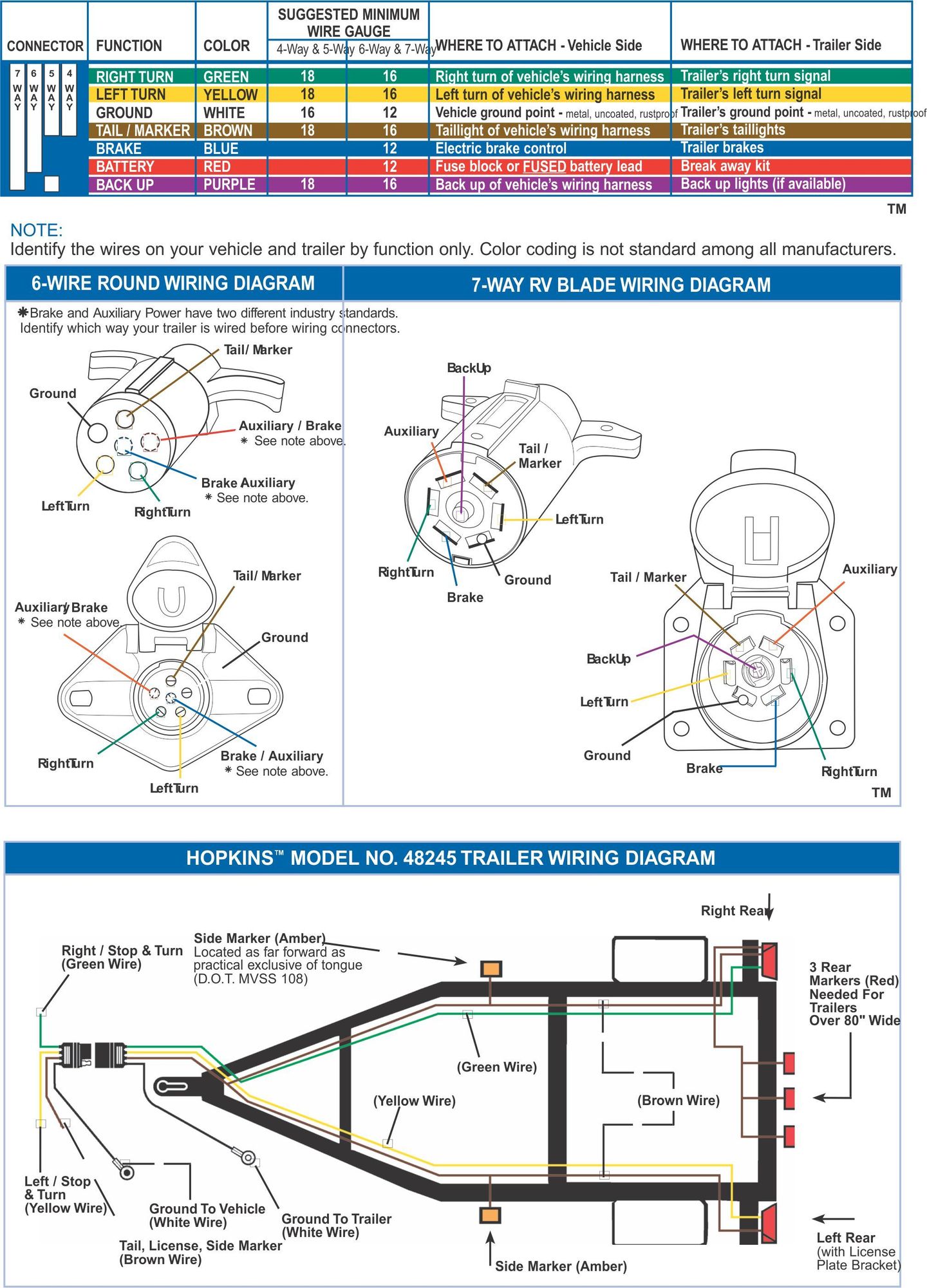
It reveals the parts of the circuit as streamlined shapes as well as the power and signal connections in between the gadgets. When wiring a trailer connector, it is best to wire by function, as wire colors can vary. This report will be talking forest river travel trailer wiring diagram.
We have an excellent wiring diagram on our website, i will provide you a link so you. It really is supposed to assist all of the typical person in developing a correct program. Here's a sample diagram of an electrical system that uses a converter.
A wiring diagram is a simplified standard pictorial depiction of an electrical circuit. Need to know which color wire go to which post. Collection of rv cable and satellite wiring diagram.
Use the rv electrical diagram we made below to get an understanding of what powers what and to learn how an rv electrical system works. Assortment of rv converter wiring schematic. Your rv has two separate electrical systems:
This chart is a typical guide, wire colors may vary based on manufacturers. In fact, that is probably an understatement. A wiring diagram is a streamlined standard photographic representation of an electrical circuit.
A motorhome is a complex electrical device. Each component ought to be set and connected with different parts in particular manner. With that being said, here are some great explanation videos to help you get a better feeling for how all this stuff works and why
It shows the parts of the circuit as simplified forms, and also the power and signal connections in between the gadgets. A wiring diagram is a streamlined traditional photographic depiction of an electric circuit. It is often found on newer trucks and suvs that come equipped from the factory with a trailer hitch.
It’s a typical trailer wiring diagram / schematic for most trailers. Typical trailer wiring diagram and schematic. Travel trailer slide out wiring diagram rv slide out wiring diagram travel trailer slide out wiring diagram people comprehend that trailer is a vehicle comprised of rather complicated mechanisms.
4 pin trailer wiring diagram One rv, two electrical systems. If not, the arrangement will not function as it ought to be.
Use a circuit tester to verify connections. Collection of travel trailer wiring schematic. Now, most electrical experts will agree that the converter that comes from the factory in most rvs, while functional, is not the best method for charging your house batteries.
Expand the same for additional axles. A small version of the map (or wiring diagram) is shown here. And we offer so much more than that!
2004 lexus es330 radio wiring diagram. Only the (blue) brake and (white) ground wires are different. If your vehicle is not equipped with a working trailer wiring harness, there are a number of different solutions to provide the perfect fit for your specific vehicle.
Above we have describes the main types of trailer wiring diagrams. Click for the complete trailer wiring diagrams article where you’ll find the full size diagrams and a ton of other information about trailer lights and wires. Below is a rv electric wiring diagram or schematic including the converter and inverter for a generic rv.
To connect the electric system of your trailer to the vehicle, you will be using special connector. Stop into our harrisburg, pa dealership today or call to learn more! We're happy to help guide our customers to the right trailer or snow plow for them.
See more ideas about trailer wiring diagram, trailer, utility trailer. Below is the generic schematic of how the wiring goes. It reveals the components of the circuit as simplified forms, as well as the power and signal links between the devices.
This automobile is designed not just to travel 1 location to another but also to carry heavy loads.
 Trailer Wiring Diagrams for Single Axle Trailers and
 Elektrische installatie in 2020 Camper busjes, Camper
 16+ Chevy Truck Front Suspension Diagram
 Xantrex mobile inverter installation diagram for a typical
 Picture Aménagement camping car, Fourgon aménagé
 A tidy wiring diagram is a must. Spitfire Electrical
 Outdoor meals Enjoy a feast outside your Eagle HT travel
 Electric Brake Controller Wiring Diagram Tekonsha Prodigy
 Kenmore Dryer Wiring Diagram Auto Electrical Wiring
 RV Inverter Wiring Diagram RV Inverter Wiring Diagram
 Pin by Brittany Smith on creative camping Travel trailer
 Image result for how to wire a pontoon boat console to
 connectorwiringdiagrams.jpg Car and bike wiring
 How To Connect Airpods To Android Tv Rocker, Switch, Wire
 WAMO Stützfuß Set 560mm Ausdrehstütze KurbelStütze
 Electrical Wiring Diagram For House Electrical wiring
 Pin on TT floor plans
 Unique Wiring Diagram for Light Bar Switch diagrams